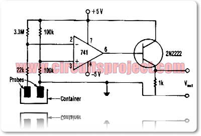
Build a simple liquid level monitor circuit diagram. The Liquid-level monitoring plays an important role in today's automotive, oil, water, pressure, pumping oil into a storage tank requires liquid-level monitoring to. This monitor uses a common 7 41 amp configured as a comparator and a low cost non transistor as an output driver. Read: Signal Tracer Injector Circuit
Liquid Level Monitor Circuit Diagram
With no liquid detected, a voltage of about 2. 92 V is present in the op amp`s inverting input at pin 2. The 100-KO resistors establish a reference voltage of +2. 5 V at the non inverting input at pin 3 of the op amp. Under those conditions, the op amp`s output is -3.56 V, which keeps the 2N2222 transistor turned off and the voltage across its 1-KO output load resistor at 0 V.
When liquid reaches the probes, the 3.3-MO and 22-KO resistor circuit conductivity connects to ground. When enough current, about 1.4 p.A, flows through the liquid, the small 30 m V drop developed across the 22-KO resistor drives the op amp to deliver an output voltage of about 4.42 V. This voltage then drives a 2N2222 transistor into saturation, which generates a voltage drop of about 3.86 V across its 1-KO output load resistor.


0 comments:
Post a Comment