Water Level Controller Detector

Water Level Controller Detector. In most houses, water is first stored in an underground tank (UGT) and from there it is pumped up to the overhead tank (OHT) located on the roof. People generally switch on the pump when their taps go dry and switch off the pump when the overhead tank starts overflowing. This results in the unnecessary wastage and sometimes non-availability of water in the case of emergency.  The simple circuit presented here makes this system automatic, i.e. it switches on the pump when the water level in the overhead tank goes low and switches it off as soon as the water level reaches a pre-determined level. It also prevents ‘dry run’ of the pump in case the level in the underground tank goes below the suction level. 

  Water Level Contoroller Circuit diagram
In the figure, the common probes connecting the underground tank and the overhead tank to +9V supply are marked ‘C’. The other probe in underground tank, which is slightly above the ‘dry run’ level, is marked ‘S’. The low-level and high-level probes in the overhead tank are marked ‘L’ and ‘H’, respectively.  When there is enough water in the underground tank, probes C and S are connected through water.As a result,transistor T1 gets forward biased and starts conducting. This, in turn, switches transistor T2 on. 

Initially, when the overhead tank is empty, transistors T3 and T5 are in cut-off state and hence pnp transistors T4 and T6 get forward biased via resistors R5 and R6, respectively.  As all series-connected transistors T2, T4, and T6 are forward biased, they conduct to energise relay RL1 (which is also connected in series with transistors T2, T4, and T6). Thus the supply to the pump motor gets completed via the lower set of relay contacts (assuming that switch S2 is on) and the pump starts filling the overhead tank. 

Water Level Contoroller Tank Circuit

Once the relay has energised, transistor T6 is bypassed via the upper set of contacts of the relay. As soon as the water level touches probe L in the overhead tank, transistor T5 gets forward biased and starts conducting. This, in turn, reverse biases transistor T6, which then cuts off. But since transistor T6 is bypassed through the relay contacts, the pump continues to run. The level of water continues to rise.  When the water level touches probe H, transistor T3 gets forward biased and starts conducting. This causes reverse biasing of transistor T4 and it gets cut off. As a result, the relay de-energises and the pump stops. Transistors T4 and T6 will be turned on again only when the water level drops below the position of L probe. 

Presets VR1, VR2, and VR3 are to be adjusted in such a way that transistors T1, T3, and T5 are turned on when the water level touches probe pairs C-S, C-H, and C-L, respectively. Resistor R4 ensures that transistor T2 is ‘off’ in the absence of any base voltage. Similarly, resistors R5 and R6 ensure that transistors T4 and T6 are ‘on’ in the absence of any base voltage. Switches S1 and S2 can be used to switch on and switch off, respectively, the pump manually.  You can make and install probes on your own as per the requirement and facilities available. However, we are describing here how the probes were made for this prototype. 

The author used a piece of non-metallic conduit pipe (generally used for domestic wiring) slightly longer than the depth of the overhead tank. The common wire C goes up to the end of the pipe through the conduit. The wire for probes L and H goes along with the conduit from the outside and enters the conduit through two small holes bored into it as shown in Fig. 2. Care has to be taken to ensure that probes H and L do not touch wire C directly. Insulation of wires is to be removed from the points shown. The same arrangement can be followed for the underground tank also. To avoid any false triggering due to interference, a shielded wire may be used.

Read More

Snail Mail Detector Circuit Diagram

Since his letter-box is outdoors  and quite some way from the  house, the author was looking  for a simple means of knowing if  the postman had been without  having to go outside (contrary  to popular belief, the weather  isn’t always fine in the South of  France). Circuits for this kind of  ‘remote detection’ come up regularly, but always involve running cables between the letter- box and the detection circuit in  the house. Seeking to avoid running any extra cables, the author  had the idea of using the existing cables going to the doorbell,  conveniently located adjacent to  his letter-box.

The letter-box has two doors:  one  on  the  street  side  for  the  postman, and one on the gar-den side for collecting the post.  A  micro switch  is  fitted  to  the  street-side door, to light an indicator in the house showing that  the postman has been. A second  micro switch is fitted to the door  on the garden side, to turn off  the indicator once the post has  been collected. The only difficulty then remains to connect  these detectors to a remote circuit in the house that remembers  whether  the  postman’s  been or not. 

 Snail Mail Detector1

Snail Mail Detector2
 
The idea was to use the alternating half-cycles of the AC signal  on the cable going to the door-bell  to  transmit  the  information, according to the following logic:
  • Both  half-cycles  present: no change in the status of the mail detector.
  • An interruption (even brief) of one half-cycle: indicator lights permanently.
  • An interruption (even brief) of the other half-cycle: the indicator goes out.
Note that the signal is tapped off  across the doorbell coil via R6  and the pair of diodes connected  in inverse-parallel (to limit the  signal,  par ticularly  when  the  bell is rung). The signal is then  filtered by R2/C1, before being  used by IC1, which is wired as a  comparator with hysteresis. The  trigger threshold is adjusted by  P1, using a pair of inverse parallel diodes as a voltage reference  (positive or negative according  to the output state):
 
For the detection to work, there  has to be continuity in the bell-push circuit this is generally  ensured by the little lamp illuminating the bell-push. Resistor R1  is added just in case the lamp is  blown or not present. To keep things simple, the circuit is powered directly from the  doorbell transformer itself (230 V  / 8 V). The author managed to fit  the little circuit within the door-bell unit, with the LED poking  through a hole in the casing so  it is readily visible in the hall of  his house. 

Author : Philippe Temporelli (France) – Copyright : elektor electronics
Read More

DTMF Proximity Detector Circuit Diagram

A DTMF-based IR transmitter and receiver pair can be used to realize a proximity detector. The circuit presented here enables you to detect any object capable of reflecting the IR beam and moving in front of the IR LED photo-detector pair up to a distance of about 12 cm from it. The circuit uses the commonly available telephony ICs such as dial-tone generator 91214B/91215B (IC1) and DTMF decoder CM8870 (IC2) in conjunction with infrared LED (IR LED1), photodiode D1, and other components as shown in the figure. A properly regulated 5V DC power supply is required for operation of the circuit.

The transmitter part is configured around dialer IC1. Its row 1 (pin 15) and column 1 (pin 12) get connected together via transistor T2 after a power-on delay (determined by capacitor C1 and resistors R1 and R16 in the base circuit of the transistor) to generate DTMF tone (combination of 697 Hz and 1209 Hz) corresponding to keypad digit “1” continuously. LED 2 is used to indicate the tone output from IC3. This tone output is amplified by Darlington transistor pair of T3 and T4 to drive IR LED1 via variable resistor VR1 in series with fixed 10-ohm resistor R14. Thus IR LED1 produces tone-modulated IR light.

DTMF Proximity Detector circuit diagramVariable resistor VR1 controls the emission level to vary the transmission range. LED 3 indicates that transmission is taking place. A part of modulated IR light signal transmitted by IR LED1, after reflection from an object, falls on photodetector diode D1. (The photodetector is to be shielded from direct IR light transmission path of IR LED1 by using any opaque partition so that it receives only the reflected IR light.) On detection of the signal by photodetector, it is coupled to DTMF decoder IC2 through emitter-follower transistor T1.
When the valid tone pair is detected by the decoder, its StD pin 15 (shorted to TOE pin 10) goes ‘high’. The detection of the object in proximity of IR transmitter-receiver combination is indicated by LED1. The active-high logic output pulse (terminated at connector CON1, in the figure) can be used to switch on/off any device (such as a siren via a latch and relay driver) or it can be used to clock a counter, etc. This DTMF proximity detector finds applications in burglar alarms, object counter and tachometers, etc.
Read More

Simple Resistance ratio Detector Circuit Diagram

This is the Simple Resistance ratio Detector Circuit Diagram.  Photoelectric control, temperature detection and moisture sensing require a circuit that can accurately detect a given resistance ratio. A simple technique that uses an op amp as a sensing element can provide 0,5% accuracy with low parts cost. The reed-relay contacts close when the resistance of the sensor Rp equals 47% of the standard Rs.

 Simple Resistance ratio Detector Circuit Diagram

Simple Resistance ratio Detector Circuit Diagram


Adjusting either Rl or R2 provides a variable threshold; the threshold is controlled by varying R3. For the most part, the type of resistors used for Rl and R2 determines the accuracy and stability of the circuit. With metal-film resistors, less than 0.5% change in ratio sensing occurs over the commercial temperature range (0 to 70 C) with ac input variations from 105 to 135 V.

Read More

Electromagnetic Field Detector Circuit Diagram

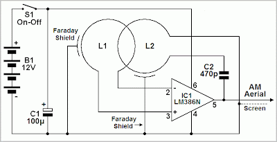
This circuit is sensitive to low frequency electromagnetic radiation and will detect for example hidden wiring or the field that encompasses a transformer. Pickup is by a radial type inductor, used as a probe which responds well to low frequency changing magnetic and electric fields. Ordinary headphones are used to for detection. The field that surrounds a transformer is heard as a 50 or 60Hz buzz. The circuit is below:-

Electromagnetic Field Detector Circuit Diagram
Detector-Circuit-Diagram
Notes:
I threaded a length of screened cable through an old pen tube and soldered the ends to a radial type can inductor. I used 1mH. The inductor fitted snugly into the pen tube. The opposite end of the cable connects to the input of the op-amp. Any op-amp should work here, possibly better results may be achieved with a low noise FET type such as the LF351. The 2M2 potentiometer acts as a gain control and the output is a pair of headphones. Stereo types can be used if they are wired as mono. I used an 8 ohm type, but the circuit should work equally well with higher impedance types. The probe (shown below) may be connected via screened cable and a 3.5mm stereo plug and socket.


Field-Detector-Circuit-Diagram
Detection:
The sensitivity of this circuit is good. Mains wiring buried an inch in plaster can be detected with precision. A small load on the electric supply is all that is needed; a 20 watt desk lamp or similar will suffice. The hum field surrounding a transformer can be detected oat over 7 inches. Domestic appliances such as videos and alarm clocks all produce interference which can be heard with the probe. The electric field surrounding a loudspeaker or earpiece can also be heard. Try lifting a telephone and place the probe near the earpiece. A telephone pickup coil can be used in place of the inductor if desired. I will make an improved version of this circuit with a meter output later.
Read More

Sensor and Detector Liquids Circuit Diagram

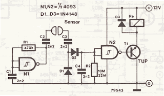
This is a very simple liquid detector which controls a relay, this gives you the option to be used for hundreds of applications. You can use it as a float switch to turn on the water pump alarm, rain, etc.. He uses a 4093 IC and transistor can be anyone, provided that it meets the power relay. This sensor can be used with Arduino no problem .


Sensor and Detector Liquids Circuit Diagram


Sensor and Detector Liquids Circuit Diagram

Read More

Metal Detectors CCO schematic Diagram

This is a schematic of a simple metal detector that uses technology CCO, by Coil Coupled Operation. Thomas Scarborough designed this new incarnation of the metal detector, a new genre that he invented in 2004. This is the first project of the Internet and can be built easily.  


 Metal Detectors CCO Schematic Diagram


Metal Detectors BCC schematic Diagram
Read More

Environmental Noise Ratio Detector Circuit Diagram

This circuit is called the detector noise environment, and also indicates by means of a flashing LED when exceeding the limit specified in the environmental noise, chosen from three fixed levels. This circuit uses two operational amplifiers, in the first position SW1 circuit is not connected, positions 2, 3 and 4 define the input sensitivity threshold to 85, 70 and 50 dB, respectively.

Environmental Noise Ratio Detector Circuit Diagram

Environmental Noise Ratio Detector Circuit Diagram


Parts List

R1 = 10K
R3 R2 = 22K
R4 = 100K
R5, R9, R10 = 56K
R6 = 5K6
R7 = 560R
R8 = 2K2
R11 = 1K
R12 = 33K
R13 = 330R
C1 = 100nF
C2 = 10μF 25V
CAP 470UF 25V C3 =
C4 = 47μF 25V
D1 = LED red
IC1 = LM358
Q1 = BC327
MIC1 = Miniature electret microphone
B1 = 9V
Read More

Detector Wireless Electricity Circuit Diagram

This is a Simple Detector Wireless Electricity Circuit Diagram. This is more of those circuits quite simple, but very useful, especially in the electrical area. This detector is an electric probe, which can also be used to detect the presence of high voltage on the wires and also as a touch switch, then the LED may be replaced with a relay to connect and disconnect a device (but only when something is detected). 

The circuit is very simple and consists of only three transistors, 3 resistors, 1 LED and a 9V battery. He has a high gain by being in Darlington transistors, and the probe (copper strip) is a small piece of copper or a wire.

 Detector Wireless Electricity Circuit Diagram

Simple Detector Wireless Electricity Circuit Diagram

Read More

BFO Metal detectors Circuit Diagram

This metal detector circuit consists of two oscillators, both working at about 465 kHz. One uses a transformer and the other uses an inductor which is the search coil LI. The oscillators are coupled through a capacitor 10 pF. The circuits DE metal detector is a BFO (beat frequency oscillator), a tone beat produced if the two oscillators are working together through the diode is detected and sent to the audio amplifier. 

 BFO Metal detectors Circuit Diagram

BFO Metal detectors Circuit Diagram


The oscillator coil is tuned by a variable capacitor of 10-365 pf variable. The search coil is made of wire with 22 turns between 24 and 36 AWG enamel junction to the center. The wire should be wound on a form of about 6 "χ 6" and the phones must be high impedance.
Read More

Room Noise Detector Schematic Circuit Diagram

This Room Noise Detector Schematic circuit diagram is intended to signal, through a flashing LED, the exceeding of a fixed threshold in room noise, chosen from three fixed levels, namely 50, 70 & 85 dB. Two Op-amps provide the necessary circuit gain for sounds picked-up by a miniature electret microphone to drive a LED. With SW1 in the first position the circuit is off. Second, third and fourth positions power the circuit and set the input sensitivity threshold to 85, 70 & 50 dB respectively. Current drawing is 1mA with LED off and 12-15mA when the LED is steady on.

Room Noise Detector Schematic Circuit Diagram

Room Noise Detector Schematic Circuit Diagram
Room Noise Detector Circuit diagram

Parts List :

R1____________10K 1/4W Resistor
R2,R3_________22K 1/4W Resistors
R4___________100K 1/4W Resistor
R5,R9,R10_____56K 1/4W Resistors
R6_____________5K6 1/4W Resistor
R7___________560R 1/4W Resistor
R8_____________2K2 1/4W Resistor
R11____________1K 1/4W Resistor
R12___________33K 1/4W Resistor
R13__________330R 1/4W Resistor

C1___________100nF 63V Polyester Capacitor
C2____________10µF 25V Electrolytic Capacitor
C3___________470µF 25V Electrolytic Capacitor
C4____________47µF 25V Electrolytic Capacitor

D1_____________5mm. Red LED

IC1__________LM358 Low Power Dual Op-amp

Q1___________BC327 45V 800mA PNP Transistor

MIC1_________Miniature electret microphone

SW1__________2 poles 4 ways rotary switch

B1___________9V PP3 Battery

Clip for PP3 Battery

Use :
  • Place the small box containing the circuit in the room where you intend to measure ambient noise.
  • The 50 dB setting is provided to monitor the noise in the bedroom at night. If the LED is steady on, or flashes bright often, then your bedroom is inadequate and too noisy for sleep.
  • The 70 dB setting is for living-rooms. If this level is often exceeded during the day, your apartment is rather uncomfortable.
  • If noise level is constantly over 85 dB, 8 hours a day, then you are living in a dangerous environment.
Read More

Simple Proximity Detector Circuit Diagram

Proximity Detector Circuit Diagram. This proximity detector is constructed using an infrared diode detector. Infrared detector can be used in various equipment such as burglar alarms, touch free proximity switches for turning on a light, and solenoid-controlled valves for operating a water tap. Briefly, the circuit consists of an infrared transmitter and an infra-red receiver (such as Siemens SFH506-38 used in TV sets).

  The transmitter part consists of two 555 timers (IC1 and IC2) wired in astable mode, as shown in the figure, for driving an infrared LED. A burst output of 38 kHz, modulated at 100 Hz, is required for the infrared detector to sense the trans mission; hence the setup as shown is required.  To save power, the duty cycle of the 38kHz astable multivibrator is maintained at 10 per cent.  The receiver part has an infrared detector comprising IC 555 (IC3), wired for operation in monostable mode, followed by pnp transistor T1. Upon reception of infrared signals, the 555 timer (mono) is turned  ‘on’ and it re-mains  ‘on’ as long as the infrared signals are being received.

Proximity Detector Circuit Diagram :

Proximity Detector Circuit Diagram
  
Proximity Detector Circuit Diagram
 
When no more signals are received, the mono goes  ‘off’ after a few seconds (the delay depends on timing resistor-capacitor combination of R7-C5). The de-lay obtained using 470kilo-ohm resistor and 4.7µF capacitor is about 3 seconds. Unlike an ordinary mono, the capacitor in this mono is allowed to charge only when the reception of the signal has stopped, because of the pnp transistor T1 that shorts the charging capacitor as long as the output from IR receiver module is available (active low).  This setup can be used to detect proximity of an object moving by. Both transmitter and receiver can be mounted on a single breadboard/PCB, but care should be taken that infrared receiver is behind the infrared LED, so that the problem due to infrared leak-age is obviated.  

An object moving nearby actually reflects the infrared rays from the infrared LED. As the infrared receiver has a sensitivity angle of 60o, the IR rays are sensed within this lobe and the mono in the receiver section is triggered. This principle can be used to turn ‘on’ the light, using a relay, when a person comes nearby. The same automatically turns  ‘off’ after some time, as the person moves away. The sensitivity depends on the current limiting resistor in series with the infrared LED. It is ob-served that with in circuit resistance of preset VR1 set at 20 ohms, the object at a distance of about 25 cms can be sensed.  This circuit can be used for burglar alarms based on beam interruption, with the added advantage that the transmitter and receiver are housed in the same enclosure, avoiding any wiring problems.
Read More

Build a High-Performance Interruption Detector Circuit Diagram

How to Build a High-Performance Interruption Detector Circuit Diagram. The circuit presented here detects interruption in security systems. Its features include no false triggering by external factors (such as sun-light and rain), easy relative positioning of the sensors and alignment of the circuit, high sensitivity, and reliability. The circuit comprises three sections, namely, transmitter, receiver, and power supply. The transmitter generates modulated IR signals and the receiver detects the change in IR intensity. Power supply provides regulated +5V to the transmitter and the receiver. 

The power supply and the speaker are kept inside the premises while the transmitter and the receiver are placed oppo site to each other at the entrance where the detection is needed. Three connections (Vcc, GND, and SPKR) are needed from the power supply/speaker to the receiver section, while only two connections (Vcc and GND) are required to the transmitter. The transmitter is basically an astable multivibrator configured around NE555 (IC3). Its frequency should match the frequency of the detector/sensor module (36 kHz for the module shown in figure) in the receiver. The transmitter frequency is adjusted by preset VR2. For making the duty cycle less than 50 per cent, di-ode 1N4148 is connected in the charging path of capacitor C7. 

The output of astable multivibrator modulates the IR signal emitted from IR LEDs that are used in series to obtain a range of 7 metres (maximum). To increase the range any further, the transmitted power has to be raised by using more number of IR LEDs. In such a case, it is advisable to use another pair of IR LEDs and 33-ohm series resistor in parallel with the existing IR LEDs and resistor R5 across points X and Y. The receiver unit consists of a monostable multivibrator built around NE555 (IC2), a melody generator, and an IR sensor module. The output of the IR sensor module goes high in the standby mode or when there is continuous presence of modulated IR signal.

High-Performance Interruption Detector Circuit diagram :
High-Performance-Interruption-Detector-Circuit-Diagram
High-Performance Interruption Detector Circuit Diagram
 
When the IR signal path is blocked, the output of the sensor module still re-mains high. However, when the block is removed, the output of the sensor module briefly goes low to trigger monostable IC3. This is due to the fact that the sensor module is meant for pulsed operation. Thus interruption of the IR path for a brief period gives rise to pulsed operation of the sensor module. Once monostable IC2 gets triggered, its output goes high and stays in that state for the duration of its pulse width that can be controlled by preset VR1. The high output at pin 3 of the monostable makes the musical IC to function. Voltage divider comprising R2 and R3 reduces the 555 output voltage to a safer value (around 3V) for UM66 operation. The du-ration of the musical notes is set by pre-set VR1 as stated earlier. 

For proper operation of the circuit, use 7.5V to 12V power supply. A battery backup can be provided so that the circuit works in the case of power failure also. Potmeter VR3 serves as a volume control. The transmitter, receiver, and power supply units should be assembled separately. The transmitter and the receiver should have proper coverings (booster) for protection against rain. The length of the wire used for connecting the IR sensor module and IR LEDs should be minimum. 

Note. 
 
The heart of the circuit is the IR sensor module (usually used in VCRs and TVs with remote); the circuit works satisfactorily with various makes of sensors. The entire circuit can be fixed in the same cabinet if the connection wires to the sensors are smaller than 1.5 meters. The reflection property of IR signals can also be used for small distance coverage.
Read More

Audio Top Detector Circuit Diagram

This audio peak detector allows a pair of stereo channels to be monitored on a sin-gle LED. Identical circuitry is used in the left and right channels. Use is made of the switch-ing levels of Schmitt trigger NAND gates inside the familiar 4093 IC. The threshold level for gate IC1.A (IC1.B) is set with the aid of preset P1, which supplies a high-impedance bias level via R2 (R1). 

Audio Top Detector Circuit diagram :

 
Simple Audio Peak Detector-Circuit-Diagram
Simple Audio Peak Detector Circuit Diagram 

When, owing to the instantaneous level of the audio signal superimposed on the bias voltage by C3 (C2), the dc level at pins 1 and 2 (5 and 6) of the Schmitt trigger gate drops below a certain level, the output of IC1.A (IC1.B) will go High. This level is copied to the input of IC1.C via D2 (D1) and due to the inverting action of IC1.C, LED D3 will light. Network R3-C1 provides some delay to enable very short audio peaks to be reliably indicated. Initially turn the wiper of P1 to the +12 V extreme — LED D3 should remain out. 

Then apply ‘line’ level audio to K1 and K3, preferably music with lots of peaks (for example, drum ‘n bass). Carefully adjust P1 until the peaks in the music are indicated by D3. The circuit has double RCA connectors for the left and right channels to obviate the use of those rare and expensive audio splitter (‘Y’) cables. 


Author : Flemming Jensen – Copyright : Elektor Electronic
Read More

Invisible Broken Wire Detector Circuit Diagram

This is a project of Invisible Broken Wire Detector Circuit diagram. Portable loads such as video cameras, halogen flood lights, electrical irons, hand drillers, grinders, and cutters are powered by connecting long 2- or 3-core cables to the mains plug. Due to prolonged usage, the power cord wires are subjected to mechanical strain and stress, which can lead to internal snapping of wires at any point. In such a case most people go for replacing the co e/cable, as finding the exact loca Portable loads such as video cameras, halogen flood lights, electrical irons, hand drillers, grinders, and cutters are powered by connecting long 2- or 3-core cables to the mains plug. Due to prolonged usage, the power cord wires are subjected to mechanical strain and stress, which can lead to internal snapping of wires at any point.

 In such a case most people go for replacing the core/cable, as finding the exact location of a broken wire is difficult. In 3-core cables, it appears almost impossible to detect a broken wire and the point of break without physically disturbing all the three wires that are concealed in a PVC jacket.  The circuit presented here can easily and quickly detect a broken/faulty wire and its breakage point in 1-core, 2-core, and 3-core cables without physically disturbing wires.  It is built using hex inverter CMOS CD4069. Gates N3 and N4 are used as a pulse generator that oscillates at around 1000 Hz in audio range.

The frequency is determined by timing components comprising resistors R3 and R4, and capacitor C1. Gates N1 and N2 are used to sense the presence of 230V AC field around the live wire and buffer weak AC voltage picked from the test probe. The voltage at output pin 10 of gate N2 can enable or inhibit the oscillator circuit. When the test probe is away from any high-voltage AC field, output pin 10 of gate N2 remains low. As a result, diode D3 conducts and inhibits the oscillator circuit from oscillating. Simultaneously, the output of gate N3 at pin 6 goes ‘low’ to cut off transistor T1. As a result, LED1 goes off. 

When the test probe is moved closer to 230V AC, 50Hz mains live wire, during every positive halfcycle, output pin 10 of gate N2 goes high. Thus during every positive half-cycle of the mains frequency, the oscillator circuit is allowed to oscillate at around 1 kHz, making red LED (LED1) to blink. (Due to the persistence of vision, the LED appears to be glowing continuously.) This type of blinking reduces consumption of the current from button cells used for power supply.  A 3V DC supply is sufficient for powering the whole circuit. AG13 or LR44 type button cells, which are also used inside laser pointers or in LED-based continuity testers, can be used for the circuit.

Invisible Broken Wire Detector Circuit diagram :


Invisible Broken Wire Detector Circuit diagram
Invisible Broken Wire Detector Circuit Diagram

The circuit consumes 3 mA during the sensing of AC mains voltage. For audio-visual indication, one may use a small buzzer (usually built inside quartz alarm time pieces) in parallel with one small (3mm) LCD in place of LED1 and resistor R5. In such a case, the current consumption of the circuit will be around 7 mA. Alternatively, one may use two 1.5V R6- or AA-type batteries. Using this gadget, one can also quickly detect fused small filament bulbs in serial loops powered by 230V AC mains. 

 The whole circuit can be accommodated in a small PVC pipe and used as a handy broken-wire detector. Before detecting broken faulty wires, take out any connected load and find out the faulty wire first by continuity method using any multimeter or continuity tester. 

Then connect 230V AC mains live wire at one end of the faulty wire, leaving the other end free. Connect neutral terminal of the mains AC to the remaining wires at one end. However, if any of the remaining wires is also found to be faulty, then both ends of these wires are connected to neutral. 

For single-wire testing, connecting neutral only to the live wire at one end is sufficient to detect the breakage point.  In this circuit, a 5cm (2-inch) long, thick, single-strand wire is used as the test probe. To detect the breakage point, turn on switch S1 and slowly move the test probe closer to the faulty wire, beginning with the input point of the live wire and proceeding towards its other end.LED1 starts glowing during the presence of AC voltage in faulty wire. When the breakage point is reached, LED1 immediately extinguishes due to the non-availability of mains AC voltage. The point where LED1 is turned off is the exact broken-wire point.  While testing a broken 3-core rounded cable wire, bend the probe’s edge in the form of ‘J’ to increase its sensitivity and move the bent edge of the test probe closer over the cable. During testing avoid any strong electric field close to the circuit to avoid false detection. 


Author :  K. Udhaya Kumaran Vu3gth - Copyright : EFY
Read More

Invisible Broken Wire Detector Circuit Diagram

Build a Invisible Broken Wire Detector Circuit Diagram. Portable loads such as video cameras, halogen flood lights, electrical irons, hand drillers, grinders, and cutters are powered by connecting long 2- or 3-core cables to the mains plug. Due to prolonged usage, the power cord wires are subjected to mechanical strain and stress, which can lead to internal snapping of wires at any point. In such a case most people go for replacing the core/cable, as finding the exact location of a broken wire is difficult.

In 3-core cables, it appears almost impossible to detect a broken wire and the point of break without physically disturbing all the three wires that are concealed in a PVC jacket. The circuit presented here can easily and quickly detect a broken/faulty wire and its breakage point in 1-core, 2-core, and 3-core cables without physically disturbing wires. It is built using hex inverter CMOS CD4069.

Gates N3 and N4 are used as a pulse generator that oscillates at around 1000 Hz in audio range. The frequency is determined by timing components comprising resistors R3 and R4, and capacitor C1. Gates N1 and N2 are used to sense the presence of 230V AC field around the live wire and buffer weak AC voltage picked from the test probe. The voltage at output pin 10 of gate N2 can enable or inhibit the oscillator circuit.

When the test probe is away from any high-voltage AC field, output pin 10 of gate N2 remains low. As a result, diode D3 conducts and inhibits the oscillator circuit from oscillating. Simultaneously, the output of gate N3 at pin 6 goes ‘low’ to cut off transistor T1. As a result, LED1 goes off. When the test probe is moved closer to 230V AC, 50Hz mains live wire, during every positive half-cycle, output pin 10 of gate N2 goes high.

Thus during every positive half-cycle of the mains frequency, the oscillator circuit is allowed to oscillate at around 1 kHz, making red LED (LED1) to blink. (Due to the persistence of vision, the LED appears to be glowing continuously.) This type of blinking reduces consumption of the current from button cells used for power supply. A 3V DC supply is sufficient for powering the whole circuit.

Invisible Broken Wire Detector Circuit Diagram

Invisible Broken Wire Detector
 Invisible Broken Wire Detector Circuit Diagram

AG13 or LR44 type button cells, which are also used inside laser pointers or in LED-based continuity testers, can be used for the circuit. The circuit consumes 3 mA during the sensing of AC mains voltage. For audio-visual indication, one may use a small buzzer (usually built inside quartz alarm time pieces) in parallel with one small (3mm) LCD in place of LED1 and resistor R5. In such a case, the current consumption of the circuit will be around 7 mA.

Alternatively, one may use two 1.5V R6- or AA-type batteries. Using this gadget, one can also quickly detect fused small filament bulbs in serial loops powered by 230V AC mains.
The whole circuit can be accommodated in a small PVC pipe and used as a handy broken-wire detector. Before detecting broken faulty wires, take out any connected load and find out the faulty wire first by continuity method using any multimeter or continuity tester.

Then connect 230V AC mains live wire at one end of the faulty wire, leaving the other end free. Connect neutral terminal of the mains AC to the remaining wires at one end. However, if any of the remaining wires is also found to be faulty, then both ends of these wires are connected to neutral. For single-wire testing, connecting neutral only to the live wire at one end is sufficient to detect the breakage point.

In this circuit, a 5cm (2-inch) long, thick, single-strand wire is used as the test probe. To detect the breakage point, turn on switch S1 and slowly move the test probe closer to the faulty wire, beginning with the input point of the live wire and proceeding towards its other end. LED1 starts glowing during the presence of AC voltage in faulty wire. When the breakage point is reached, LED1 immediately extinguishes due to the non-availability of mains AC voltage.

The point where LED1 is turned off is the exact broken-wire point. While testing a broken 3-core rounded cable wire, bend the probe’s edge in the form of ‘J’ to increase its sensitivity and move the bent edge of the test probe closer over the cable. During testing avoid any strong electric field close to the circuit to avoid false detection.

Author: K. Udhaya Kumaran
Read More