How To Build A Simple 5 V USB Solar Charger (No Battery)?

 How to build Simple 5 V USB Solar Charger (No Battery)? Charge phones/power 5 V gadgets directly in sunlight.

Chosen specs

  • Panel: 15 W “12 V” nominal mono panel, Vmp ≈ 18 V, Voc ≈ 22 V, Isc ≈ 0.9 A (common size ~300×350 mm)

  • Output: 5.0 V regulated, up to ~2 A peak (realistic ~1–1.5 A in good sun)

Topology

Panel → blocking diode → buck converter (to 5.00 V) → USB-A


Panel + ── Fuse(2A) ──|<|── +IN  Buck (LM2596 or MP1584)  +OUT ── +5V → USB-A pin 1

            D1: SS34   |                         

Panel − ─────────────────────── GND ───────────────── GND → USB-A pin 4

                             TVS(SMBJ24A) across +IN↔GND (optional)


BoM (example parts)

  • Solar Panel: 15 W, 12 V nominal, Vmp ~18 V, Isc ~0.9 A

  • D1 Blocking Diode: SS34 (3 A, 40 V Schottky) — low drop, low reverse leakage

  • Buck Module: LM2596 (3 A rated) or MP1584EN-based mini buck (3 A rated)

  • USB-A Female Jack: panel-mount or PCB type

  • Fuse (Panel+): 2 A blade or mini inline

  • TVS Diode (optional): SMBJ24A across buck input

  • Cable: 20–22 AWG for short USB, 18 AWG from panel to buck if >0.5 m

  • Enclosure: Small IP65 junction box, cable glands

Build notes

  • Set buck to 5.00 V with a multimeter before connecting a device.

  • Many LM2596-USB boards include data-pin resistors for phone charging. If using a plain USB jack, add 49.9 kΩ pull-downs or a “dumb charger” divider (D+/D− short or 2.0 V/2.7 V depending on device). Most modern phones accept D+/D− short.

  • Mount SS34 in series with panel + (stripe towards buck).

Testing

  1. Measure panel Voc in sun: ~20–22 V.

  2. With panel connected and no load, verify buck input 16–20 V, output 5.00 V.

  3. Plug a 5 V dummy load/phone—expect 0.5–1.5 A; output should hold 4.9–5.1 V.


Sourced By: Streampowers
Read More

Simple 100W Inverter Schematic Diagram

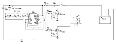
This is the Simple 100W Inverter Schematic Diagram. An inverter will convert the DC voltage to an AC voltage. In most cases, the input DC voltage is usually lower than the output voltage of the inverter while the output AC is equal to the grid supply voltage 120 volts, or 240 Volts. Lets start it.

Simple 100W Inverter Schematic Diagram


Simple 100W Inverter Schematic Diagram


Circuit Part List

Resistors
22K Resistor 3x
220 Ohm Resistor 2x
100 Ohm Resistor 1x

Diode
4007 Diode 1x
10V Zener 1x

IC
4047 IC + 14 Pin IC socket 1x

Capacitor
0.01uf capacitor 1x
100uf capacitor 1x

MOSFETS
IRF 3205 mosfet 2x

Varo Board

Transformer
Center Tap (CT) Transformer. Input 12-0-12, while the output refer to your standard home electricity (every county may different).

In the tutorial, it use 12-6-0-6-12 5 amp Transformer you can call it 120 VA transformer. You can use any kind of 12 -0-12 transformer.

Please take a note that this inverter can handle up to 100w of load but be careful, on the 100w of load you should use Heatsinks with those mosfets.

Read More

Door Opener Alarm Circuit Diagram

The door opener derives its power from a 9-V battery. A momentary-contact switch, 52, is provided in the event that manual opening and closing is required. Relay Kl is a 9-V type and relay K2 is a 117`Vac latching-type, which automatically latches with the first burst of current and opens on the second burst.

Door Opener Alarm Circuit Diagram

Door Opener Alarm Circuit Diagram


The gate lead of the LASCR is not used; a light source triggers the LASCR unit into conduction, causing current to flow in the coil of the relay. That, in turn, causes Kl`s contacts to close, thereby energizing K2 (closing its contacts), and operating the garage door motor.
Read More

Emergency Siren Simulator Circuit Diagram

This siren circuit simulates police, fire or other emergency sirens that produce an up and down wail.

Simple Emergency Siren Simulator Circuit Diagram


Emergency Siren Simulator Circuit Diagram


The heart of the circuit is the two transistor flasher with frequency modulation applied to the base of the first transistor. When the pushbutton is depressed, the frequency of oscillation climbs to a peak and when the button is released, the frequency descends due to the rising and falling voltage on the 22 uF capacitor. The rate of change is determined by the capacitor value and the 100k resistor from the pushbutton.  The oscillation eventually stops if the button is not depressed and the current consumption drops to a tiny level so no power switch is needed.

The 0.1 uF determines the pitch of the siren: A 0.047uF will give a higher pitch siren and a 0.001 uF will give an ultrasonic (at least for me, anyway) siren from 15 to 30 kHz which might have an interesting effect on the neighborhood dogs! The 33k resistor from the collector of the PNP to the base of the NPN widens the pulse to the speaker giving greater volume.

The flasher circuit drives a PNP transistor which powers the speaker. This transistor may be a small-signal transistor like the 2N4403 in most applications since it will not dissipate much power thanks to the rapid on-and-off switching. The 100 ohm and 100uF capacitor in series with the speaker limit the current to about 60 mA and they may be replaced with a short circuit for a louder siren as long as the transistor can take the increased current. The prototype drew about 120 mA when shorted which is fine for the 2N4403.

Transistor substitutions should be fine - try just about any small-signal transistors but avoid high frequency types so that you do not end up with unwanted RF oscillations.
Read More