Door Opener Alarm Circuit Diagram

The door opener derives its power from a 9-V battery. A momentary-contact switch, 52, is provided in the event that manual opening and closing is required. Relay Kl is a 9-V type and relay K2 is a 117`Vac latching-type, which automatically latches with the first burst of current and opens on the second burst.

Door Opener Alarm Circuit Diagram

Door Opener Alarm Circuit Diagram


The gate lead of the LASCR is not used; a light source triggers the LASCR unit into conduction, causing current to flow in the coil of the relay. That, in turn, causes Kl`s contacts to close, thereby energizing K2 (closing its contacts), and operating the garage door motor.
Read More

Emergency Siren Simulator Circuit Diagram

This siren circuit simulates police, fire or other emergency sirens that produce an up and down wail.

Simple Emergency Siren Simulator Circuit Diagram


Emergency Siren Simulator Circuit Diagram


The heart of the circuit is the two transistor flasher with frequency modulation applied to the base of the first transistor. When the pushbutton is depressed, the frequency of oscillation climbs to a peak and when the button is released, the frequency descends due to the rising and falling voltage on the 22 uF capacitor. The rate of change is determined by the capacitor value and the 100k resistor from the pushbutton.  The oscillation eventually stops if the button is not depressed and the current consumption drops to a tiny level so no power switch is needed.

The 0.1 uF determines the pitch of the siren: A 0.047uF will give a higher pitch siren and a 0.001 uF will give an ultrasonic (at least for me, anyway) siren from 15 to 30 kHz which might have an interesting effect on the neighborhood dogs! The 33k resistor from the collector of the PNP to the base of the NPN widens the pulse to the speaker giving greater volume.

The flasher circuit drives a PNP transistor which powers the speaker. This transistor may be a small-signal transistor like the 2N4403 in most applications since it will not dissipate much power thanks to the rapid on-and-off switching. The 100 ohm and 100uF capacitor in series with the speaker limit the current to about 60 mA and they may be replaced with a short circuit for a louder siren as long as the transistor can take the increased current. The prototype drew about 120 mA when shorted which is fine for the 2N4403.

Transistor substitutions should be fine - try just about any small-signal transistors but avoid high frequency types so that you do not end up with unwanted RF oscillations.
Read More

Automatic Car Alarm Circuit Diagram

Even the best car alarm is useless if you forget to set it upon leaving your car, whence this circuit. The relay has a make and a break contact: the  former is necessary to delay the switching in of the  alarm after you have got out of your car, and the  latter serves to switch on the car alarm proper. Immediately on re-entering your car, you must press the hidden switch, Si. This causes silicon-controlled rectifier Thi to conduct so that the relay is energized. At the same time, the green LED lights to indicate that the alarm is switched off.  

Circuit diagram :

Automatic Car Alarm Circuit Diagram

 Best Automatic Car Alarm Circuit Diagram

As soon as the ignition is switched off, T, is off, T2  is on, and the buzzer sounds. At the same time,  monostable IC1 is triggered, which causes T3 to  conduct and the red LED to light. The silicon- controlled rectifier is then off, and D4 is reverse  biased, but the relay remains energized via its make  contact for a short time, preset by Pi As soon as this  time has lapsed, the relay returns to its quiescent  state, and the alarm is set via the break contact. The  delay time can be set to a maximum of about 1 minute.
Read More

Water Alarm Circuit Diagram

The LM1830 fluid detector IC from National Semiconduc tor is designed to be able to detect the presence of fluids using a probe. This chip requires a relatively high supply voltage and is not the most frugal power consumer. It is also quite specialised so unless you are buying in bulk the one-off price is not cheap. 

An alternative circuit show n her e uses a standard CMOS IC type 74HC14. It has the advantage of operating with a 3 V supply and consumes less than 1 µA when the alarm is not sounding, this makes it ideal for use with batteries. 

Water Alarm Schematic Circuit Diagram

Water Alarm Circuit Diagram


The 74HC14 has six inverters with hysteresis on their input switching thresholds. A capacitor (C1) and a feedback resistor (R1) is all that’s necessary to make an inverter into a square wave signal generator. 

In the water alarm circuit the feedback resistor consists of R1 and the water sensor in series. R1 prevents any possibility of short-circuit between the inverter’s input and out-put. Resistor R2 defines the inverter’s input signal level when the sensor is not in water. Any open-circuit (floating) input can cause the inverter to oscillate and draw more current.The remaining inverters in the package (IC1.B to IC1.F) drive the piezo buzzer to produce an alarm signal. Capacitor C2 ensures that no DC current flows when the circuit is in monitoring mode (with the alarm silent) this helps reduce the supply current. 

A micro-switch can also be substituted for the water sensor to make the circuit a more general purpose alarm generator.


Author: Roland Heimann - Copyright: Elektor
Read More

A Doorbell for the Deaf Circuit Diagram

This circuit provides a delayed visual indication when a door bell switch is pressed. In addition, a DPDT switch can be moved from within the house which will light a lamp in the door bell switch. The lamp can illuminate the words "Please Wait" for anyone with walking difficulties.


A Doorbell for the Deaf Circuit Diagram :

A Doorbell for the Deaf Circuit Diagram


Notes :
The circuit uses standard 2 wire doorbell cable or loudspeaker wire. In parallel with the doorbell switch, S1, is a 1N4001 diode and a 12 volt 60mA bulb. The bulb is optional, it may be useful for anyone who is slow to answer the door, all you need to do is flick a switch inside the house, and the bulb will illuminate a label saying Please Wait inside the doorbell switch or close to it. The double pole double throw switch sends the doorbell supply to the lamp, the 22 ohm resistor is there to reduce current flow, should the doorbell switch, S1 be pressed while the lamp is on. The resistor needs to be rated 10 watts, the 0.5 Amp fuse protects against short circuits.

When S2 is in the up position (shown as brown contacts), this will illuminate the remote doorbell lamp. When down, (blue contacts) this is the normal position and will illuminate the lamp inside the house. Switch S1 will then charge the 47u capacitor and operate the transistor which lights the lamp. As a door bell switch is only pressed momentarily, then the charge on the capacitor decays slowly, resulting in the lamp being left on for several seconds. If a longer period is needed then the capacitor may be increased in value.
Read More

Little Door Guard Circuit Diagram

If some intruder tries to open the door of your house, this circuit sounds an alarm to alert you against the attempted intrusion. The circuit (Fig. 1) uses readily available, low-cost components. For compactness, an alkaline 12V battery is used for powering the unit. Input DC supply is further regulated to a steady DC voltage of 5V by 3-pin regulator IC 7805 (IC2).

Little Door Guard Circuit Diagram

Little Door Guard Circuit Diagram


Fig. 1: Circuit of the door guard

Assemble the unit on a general-purpose PCB as shown in Fig. 4 and mount the same on the door as shown in Fig. 3. Now mount a piece of mirror on the door frame such that it is exactly aligned with the unit. Pin configurations of IC UM3561 and transistors 2N5777 and BC547 are shown in Fig. 2. 


Fig. 2: Pin configurations of UM3561 and transistors 2N5777 and BC547

Initially, when the door is closed, the infrared (IR) beam transmitted by IR LED1 is reflected (by the mirror) back to phototransistor 2N5777 (T1). The IR beam falling on phototransistor T1 reverse biases npn transistor T2 and IC1 does not get positive supply at its pin 5. As a result, no tone is produced at its output pin 3 and the loudspeaker remains silent. Resistor R1 limits the operating current for the IR LED.


When the door isopened, the absence of IR rays at phototransistor T1 forward biases npn transistor T2, which provides supply to  positiveIC1. Now 3-sirensound generator IC UM3561 (IC1) gets power via resistor R5. The output of IC1 at pin 3 is amplified by Darlington-pair transistors T3 and T4 to produce the alert tone via the loudspeaker. 


Fig. 3: Back view of the door assembly

Rotary switch S2 is used to select the three preprogrammed tones of IC1. IC1 produces fire engine, police and ambulance siren sounds when its pin 6 is connected to point F, P or A, respectively.


Author : T.K. Hareendran - Copyright : EFY
Read More

Bicycle Alarm Circuit Diagram

The author wanted a very cheap and simple alarm for some of his possessions, such as his electrically assisted bicycle. This alarm is based on a cheap window alarm, which has a time-switch added to it with a 1-minute time-out. The output  pulse of the 555 replaces the reed switch in the window alarm. The 555 is triggered by a sensor mounted near the front  wheel, in combination with a magnet that is mounted on the spokes. This sensor and the magnet were taken from a cheap bicycle computer. 

Bicycle Alarm Circuit Diagram


Cheap Bicycle Alarm Circuit Diagram

The front wheel of the bicycle is kept unlocked, so that the reed  switch closes momentarily when the wheel turns. This  triggers the 555, which in turn activates the window alarm. The circuit around the 555 takes very little current and can  be powered by the batteries in the window alarm.  There  is just enough room  left inside the enclosure of the window  alarm to mount the time-switch inside it. 

The result is a very cheap, compact device, with only a single cable going to the reed switch on the front wheel. And the noise this thing produces is just unbelievable! After about one minute the noise stops and the alarm goes back into standby mode. The bicycle alarm should be mounted in an inconspicuous place, such as underneath the saddle, inside a (large) front light, in the battery compartment, etc.
Hopefully the alarm scares any potential thief away, or at least it makes other members of the public aware that something isn't quite right. 

Caution. The installation and use of this circuit may be subject to legal restrictions in your country, state or area.


Read More

Wireless Security System Using PIR Sensors Project

This project demonstrates a wireless security system in which four pyroelectric infrared (PIR) motion sensors are placed in four sides—front, back, left and right—of the area to be covered. It detects motion from any side and turns on the audio-visual alarm. It also displays the side where the motion (intruder) is detected. All sensors send signal to the central controller circuit wirelessly. The author’s prototype arrangement is shown in Fig. 1.

Wireless Security System Using PIR Sensors Project
 Fig. 1: Author’s prototype arrangement for Wireless security system

System block diagram

System block diagram of the wireless security system is shown in Fig. 2. The project uses PIR motion sensors to detect motion and ASK-based radio frequency (RF) transmitter and receiver modules to send signals wirelessly. It uses AT89S52 microcontroller (MCU) and LCD to display the side where the motion is detected.

 Fig. 2: Block diagram of wireless security system using PIR sensors

The block diagram has two parts: four transmitter units with PIR sensors, encoders and RF transmitters; and receiver unit with RF receiver, decoder, MCU and some audio-visual circuits.

Transmitter unit

There are four transmitter blocks, one each for front, back, left and right sides. Each block consists of a PIR sensor, RF encoder chip and RF transmitter (Tx) module.

PIR sensor

The PIR sensor detects motion by measuring any change in IR levels emitted by objects. Pyroelectric devices have elements made of a crystalline material, which generate an electric current when exposed to IR radiation. Changes in the amount of IR falling on such devices changes the voltages that are generated. Sensor output goes high when it detects motion. Sensor output is given to RF encoder chip.

RF Encoder

HT12E encoder chip encodes PIR sensor output into serial bit streams and gives it to RF Tx module.

RF transmitter

ASK transmitter modulates incoming digital signals from the RF encoder using a 434MHz carrier and transmits it through its antenna.

Receiver unit

This is the central controlling section that receives signals from any of the four PIR sensors at the transmitter side. It gives audio and visual alarms, and displays the side where the motion is detected on LCD1.

RF receiver

This module operates on 434MHz frequency and demodulates the received digital signals before sending bit streams to RF decoder chip.

RF decoder

HT12D RF decoder chip decodes bit streams and generates parallel 4-bit digital output, which is given to the MCU.

MCU

AT89S52 MCU performs the following tasks:

1. Detects side where motion is detected from RF decoder digital output

2. Displays various messages including side of detected motion on LCD1

3. Turns on speaker and blinks LED for audio-visual alarm when motion is detected
LCD panel

The 16×2 LCD panel displays messages given by the MCU.

Multivibrators

There are two multivibrators. One for blinking the LED at low frequency (1Hz – 2Hz), and the other for generating the audio frequency signal (1kHz) through the speaker for siren.

Circuit and working

There are five circuits. Of these, four transmitter circuits are similar to each other, with minor changes, as shown in Fig. 3. Fifth circuit, as shown in Fig. 4, is the receiver circuit.

Wireless Security System Using PIR Sensors circuit
Fig. 3: The four transmitter circuits


Wireless Security System Using PIR Sensors circuit 1
 Fig. 4: Circuit diagram of MCU-based central receiver circuit


Transmitter circuit

The first transmitter circuit is built around IC1. Output of PIR sensor PS1 is given to data input AD8 (pin 10) of HT12E (IC1) after inverting it through transistor T1. Diodes D1 and D2 connect transmission enable (TE) pin with pin AD8, so that both pins get input from the sensor at the same time.

LED1 is connected to collector output of T1, so that it blinks when PS1 sensor output goes high. Address pins A0 through A7 of IC1 are connected to ground to set address 00 (0000 0000b). Serial data output DOUT (pin 17) is given as data input to 434MHz RF Tx module (TX1). The whole circuit is given power through 6V battery (BATT.1) connected across CON1.

The other three circuits are shown in Fig. 3 are similar to the one described above. The only difference is that the diode is connected to different data pins.

When PIR sensor PS1 detects motion, its output goes high. T1 conducts and LED1 blinks.

Pins AD8 and TE of IC1 are pulled low together through diodes D1 and D2. When TE pin is pulled low, IC1 transmits address A0 through A7, and AD8 through AD11 serially through RF Tx module. Because pin AD8 is pulled low, data bits are transmitted as 1110 (AD11 through AD8). Similarly, in other such circuits, when motion is detected, the respective data pin is pulled low, so different data is transmitted, as listed in Table I.


Thus, when a sensor detects motion from its side, different bit pattern of D0 through D3 is transmitted. At receiver side, this pattern is used to identify the side where motion is detected.
Receiver unit

As shown in Fig. 4, the receiver is built using 434MHz RF Rx module (RX1), RF decoder chip HT12D (IC5), AT89S52 MCU (IC6) and NE555 multivibrators (IC7 and IC8).


Sourced By : EFY Author:  Ashutosh M. Bhatt
Read More

Glass Break Alarm Circuit Diagram

This circuit can be used for sounding an alarm to detect the breaking of a glass window by an intruder, even when the intruder ensures there is no sound of the shattered glass.

Fig. 1: Circuit of the glass break alarm

Circuit and working
  
Fig. 1 shows the circuit diagram of the glass break alarm. It is built around a piezo element connected across connector CON2, transistor BC549 (T1), timer NE555 (IC1), a piezo buzzer (PZ1) and a few other components.

A small piezo element used in the piezo buzzer is used as a sensor. It may be fixed at the centre of the window glass. IC1 is wired in monostable multivibrator mode, which is triggered by the piezo element. Output of IC1 is used to drive piezo buzzer PZ1. LED1 indicates the high-state output at pin 3 of IC1. Time delay can be adjusted by potentiometer VR1. Use an ordinary piezo buzzer at the output to generate a warning sound. This circuit works on 9V-12V DC.

When an intruder tries to break the glass, the piezo element generates an electric pulse, which is amplified and sent to the monostable multi-vibrator (IC1). The high output of IC1 drives LED1 and also produces a sound to indicate that someone is breaking the glass.

The 9V-12V DC power supply is connected across CON1, and the piezo element is connected across connector CON2.

Construction and testing
An actual-size, single-side PCB for the glass break alarm is shown in Fig. 2 and its component layout in Fig. 3. Enclose the PCB in a suitable small box in such a way that the piezo buzzer sounds when someone tries to break the glass window. Fix the piezo element at the centre of the window glass for best results.

Fig. 2: Actual-size PCB of the glass break alarm

Fig. 3: Component layout of the PCB


Use of 8-pin IC base is recommended for IC NE555.


Sourced by: EFY. Author : Pradeep G.
Read More

Automatic Dipper for Vehicles Project

While driving a car in night a problem like many drivers do not dip the head lamps of their vehicles in night while approaching. The several switching operation is used to dip the head light which may distract the concentration. To overcome this type of problem the innovative group Dreamlover Technology designs a unique electronics gadget called “Automatic Dipper” using very popular IC NE555 and LDR.

Circuit Description

The entire circuit of automatic dipper consist LDR followed by timer IC NE555 (IC1) and few other components, where LDR is used as sensor. LDR sense the light and change its internal resistance according light fall on it, which is further mounted in PVC pipe of 4 cm length positioned on the grill of car or in front such that the light fall on the LDR only when vehicles is approaching and is distance of 3M to 9M. When light fall on it the resistance decrease and makes output of IC1 low which energized the relay. The relay operates and voltage across the head lamps is reduced. When the distance between two approaching vehicles is more than 9 meter or less than 3 meter the circuit is not operated.

Automatic Dipper for Vehicles Circuit Diagram 

Automatic Dipper for Vehicles
 

The operating and non operating distance of the circuit can be varied by proper positioning of the PVC pipe and by adjusting the variable resistor VR1.


PARTS LIST
Resistors (all ¼-watt, ± 5% Carbon)

R1 = 10 Ω/10W

VR1 = 10 KΩ
Semiconductors

IC1 = NE555 (timer IC)

D1 = 1N4001
Miscellaneous

RL1 = 12V/100 Ω

LDR1= Light dependent resistor


Sourced by:  electronicsproject
Read More

Electronic siren circuit Diagram

This is a compact electronic siren circuit based on three transistors.This circuit is suitable for in corporating with other alarm or siren projects such as burglar alarms, automatic factory sirens etc or a simple push to on alarm.

The  electronic siren circuit given here  is  based on a complementary transistor pair consisting of Q2 & Q3 (BC557 & BC 37)  wired as an astable multivibrator oscillator,which directly drives the speaker.The transistor Q1 is used to provide a full charge on capacitor C2 when power is turned ON. When push button switch S1 is pressed , the capacitor C2 slowly discharges through resistor R8.This makes the circuit to  oscillate at a low frequency that increases to a high frequency and kept indefinitely as the capacitor is fully discharged. When the switch P1 is released, the output  frequency decreases slowly as C2 is charged to the  positive voltage through resistance R6 and the Base-Emitter junction of tramsistor Q2. When C2 is fully charged to the positive battery voltage the  circuit stops oscillating.

Electronic siren circuit Diagram with Parts list.

Electronic siren circuit Diagram


Notes.

  • A 12 V battery or a a well regulated 12V DC power supply can be used to power the circuit.
  • Assemble the circuit on a good quality PCB or common board.
  • The switch S1 can be used to activate the alarm.
  • The switch S2 can be used as a power switch.
  • You can experiment on the tone of alarm by using different values for C2 and R8.


Sourced By: circuitstoday
Read More

Sensitive LPG Leakage Alarm Project

Here is an ultra-sensitive LPG sensor that generates loud beeps when it senses any gas leakage. It detects vapours of liquefied petroleum gas anywhere between 200 and 10,000 ppm and drives a piezobuzzer to catch attention for immediate action. The buzzer beeps until the concentration of gas in the air decreases to a safe level. The circuit uses an MQ6 gas sensor, which is designed to sense LPG, propane and isobutane gases.

Circuit and working
Fig. 1 shows the circuit of the LPG sensor. The circuit is built around 5V voltage regulator 7805 (IC1), gas sensor MQ6 (GS1), counter IC 4060 (IC2) and a few discrete components.

GS1 is a six-pin gas sensor that can detect very small traces of LPG in the air and has a swift response time. However, it has very less sensitivity to alcohol and smoke. The sensor’s output is in the form of resistance.

Sensitive LPG Leakage Alarm Project
Fig. 1: Circuit of the sensitive LPG sensor

As indicated in Fig. 1, the pins of GSI are H, A and B, two each on either side. H pins are for the heater with no polarity. Input pins A or B and output pins A or B can be connected either way round.


The coil heater inside the sensor can be easily heated with 5V DC. If pin A is connected to 5V DC through variable resistor VR1, use pin B as the output or vice versa. Both A and B pins can be shorted. In short, H pins are connected to positive and negative rails, A or B pin to 5V DC, and B or A for output.

The resistance value of GSI is different for various kinds and concentration of gases. So when using this sensor, sensitivity arrangement is very important. For accurate detection, it is necessary to calibrate the sensor for 1000 ppm of LPG concentration in the air with load resistance of about 20 kilo-ohms. (In the datasheet, the load resistance range of MQ6 is mentioned as 10 kilo-ohms to 47 kilo-ohms.)

Fig. 2: An actual-size, single-side PCB for sensitive LPG sensor

Fig. 3: Component layout for the PCB


Preset VR1 is used to adjust the sensitivity of the sensor to a particular gas concentration. Output from the sensor is connected to the base of transistor T1, which acts as a switch to trigger the alarm generator built around IC2.

IC2 is a binary counter IC that oscillates using capacitor C2 and resistor R5. Transistor T1 controls the reset pin (pin 12) of IC2. When the reset pin is high IC2 does not oscillate, and when this pin goes low IC2 starts oscillating.

Working of the circuit is simple. When the sensor detects LPG in the air, its output becomes high and transistor T1 conducts to make reset pin of IC2 low. This triggers IC2 to oscillate, which is indicated by LED1. After a few seconds, the buzzer starts beeping to indicate gas leakage.
 

The circuit works off 12V DC from a battery (BATT.1) or you can use an adaptor. IC1 provides regulated 5V DC supply for the sensor and IC2.

Construction and testing
An actual-size, single-side PCB for sensitive LPG sensor is shown in Fig. 2 and its component layout in Fig. 3. After assembling the circuit on a PCB, enclose it in a suitable case with an opening to allow the gas to enter. Place the unit near the LPG cylinder or gas stove within a distance of one metre. Vary preset VR1 to adjust the sensitivity of the sensor.

To test the circuit, check 12V at test point TP1 with respect to TP0 to verify the correct power supply. Place the unit near the gas stove burner and turn on the burner for a few seconds without igniting. Then, turn ’the burner ‘off’ and adjust VR1 until you see LED1 glowing. TP3 should be low at this moment.


Sourced By: EFY Author: D.Mohan Kumar
Read More

Simple Alarm Power Supply Circuit Diagram

This is simple Simple Alarm Power Supply Circuit Diagram. A 12 Volt power suppiled designed for Ron's Modular Burglar Alarm. However, being a popular supply voltage this circuit will have many other uses as well.


Simple Alarm Power Supply Circuit Diagram


Simple Alarm Power Supply Circuit Diagram


Notes
This Power Supply is suitable for the Modular Burglar Alarm. However, it has other applications. It is designed to provide an output of 12-volts, with a current of up to 1-amp. In the event of mains failure, the back-up battery takes over automatically. When the mains is restored, the battery recharges. Use a genuine alarm type back-up battery. They are maintenance-free, and their terminals can be held at 13v8 for many years, with no ill effects. A smaller or larger capacity battery may be used, without circuit modification. Use the 2-amp version of the 7805. It needs the larger heatsink because it has to dissipate a lot of energy, especially when called upon to recharge a flat battery. This heatsink is at 9v1, and must NOT be connected to ground. 


The 7812 never has to dissipate more than 2-watts, so its heatsink can be smaller.Many of the components, which are shown lying flat on the board, are actually mounted upright. The links are bare copper wire on the component side. The heatsinks are folded strips of aluminium, about 2mm thick. Use a well-insulated panel mounted fuse holder for the mains supply to the transformer, and fit it with a 1-amp fuse.


Sourced By: Zen Author: Ron J
Read More

Simple Car Alarm Arming Horn Beep Canceller Project

This is the Simple Car Alarm Arming Horn Beep Canceller Circuit Diagram Project. It's a great convenience that most modern cars come with a built in alarm, however it is nothing but noise pollution that the horn sounds when the alarm is armed. Disconnecting the alarm system from the horn relay will eliminate this, but prevent the horn from sounding in the even of an actual alarm. This circuit serves to silence the arming beep yet maintain the alarm by introducing a small delay into the signal. 
 

Car Alarm Arming Horn Beep Canceller Circuit Diagram


Car Alarm Arming Horn Beep Canceller Circuit Diagram
 
 
It sits between the alarm and horn relay. The alarm must provide a constant horn signal for at least 3 seconds before the horn relay is activated. That way the quick "beep" will never activate the horn relay, while the constant alarm signal will.


Part           Total Qty.             Description
C1                   1           0.01uF Ceramic Disc Capacitor  
C2                   1           100uF 35V Electrolytic Capacitor  
R1                   1           1K 1/4W Resistor  
R2                   1           10K 1/4W Resistor  
R3                   1           15K 1/4W Resistor  
R4                   1           470 Ohm 1/4W Resistor  
D1, D3, D4      3           1N4004 Rectifier Diode  
D2                   1           Red LED  
U1                   1           555 Timer IC  
K1                   1           SPST 12V Automotive Relay  
MISC               1          Board, Wire, Socket For U1, Case   
Read More

Simple Homemade Melody Door Bell Circuit Diagram

This is the Simple Homemade Melody Door Bell Circuit Diagram. In most of the homes the door bells are conventional ding-dong type. Most of us don’t like its sound. Due to mechanical moving parts with spring mechanism its long term durability is questionable. I had also one such door bell in my home. After a period of time its performance deteriorates and one time it becomes completely intolerable because of its noisy irritating sound.

Simple Homemade Melody Door Bell Circuit Diagram

The new types of door bells available in market are bird sound door bell. They are costly. and even I didn’t like it because of its high frequency and high volume sound output.    

Simple Homemade Melody Door Bell Circuit Diagram

Simple Homemade Melody Door Bell Circuit Diagram
 

So the idea came into my mind that why not to build a very simple door bell with few components that gives nice melodious output and that is at the less cost also. So I build this door bell with all the items available in home. Let us see how I have made it.

Description

First collect the required components

·         Transformer – 230 V to 18 V@500 mA

·         Diode bridge or 4 diodes – 1N4004

·         Capacitors – 1000 µF, 0.1 µF

·         Resistors - 560Ω

·         Voltage regulator ICs – LM7805, LM7812

·         Relay – 12 V 1 C/O

·         Transistor – 2N2222A

·         8Ω speaker

·         Melody generator IC UM66

Now build the circuit on general purpose PCB. (See the circuit diagram tab for the doorbell circuit)


Circuit description:

·         230 VAC is applied to primary of transformer with bell switch in between as shown

·         The secondary of transformer is connected to AC input terminals of diode bridge

·         A 1000 µF capacitor is connected across rectified output terminals of diode bridge

·         This output is given as input to both voltage regulator chips 7812 and 7805

·         The output of 7812 IC drives relay coil directly. A filter capacitor of 0.1 µF is connected across it.

·         The output of 7805 is given to common terminal of relay

·         The second normally open terminal of relay is connected to input of UM66 through voltage divider network made up of resistors R1 and R2

·         The output of UM66 drives 8Ω speaker through NPN type transistor Q1

Circuit operation:

·         When bell switch is pressed and hold for some time (2-3 sec) the AC supply is given to primary of transformer

·         The diode bridge rectifies AC supply available from secondary. Capacitor C1 filters it out and finally 7812 will generate 12 V and 7805 will generate 5 V

·         As relay gets 12 V, it energise and switches ON

·         So common terminal gets connected to normally open terminal and 5 V supply is given to UM66 through voltage divider. Due to same values of R1 and R2 2.5 V is given to UM66

·         UM66 generates musical sound output that is amplified by Q1 so that musical output is audible through speaker

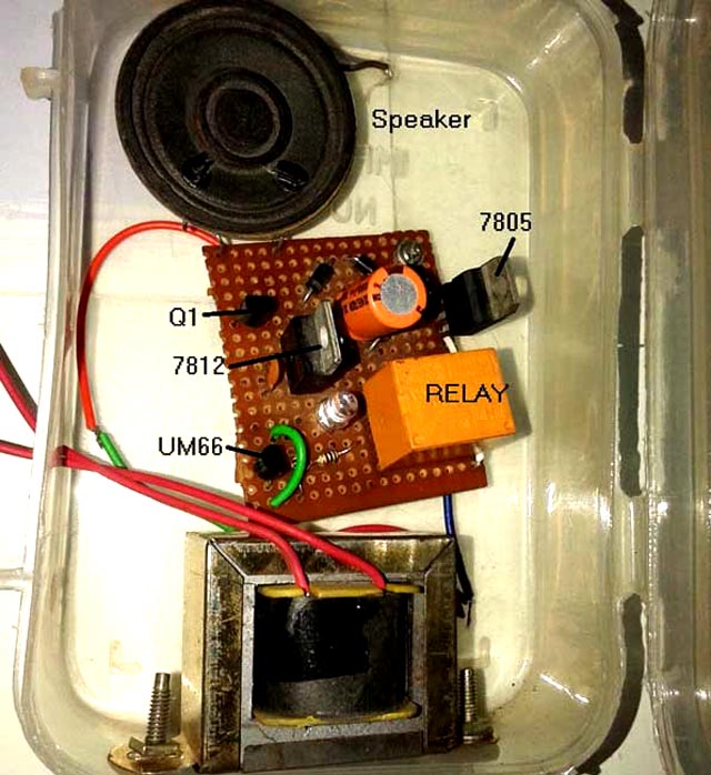
Here is the photograph of the circuit that is completely housed in a plastic box. The plastic box is hanged on the wall at the place where wire connections for door bell are given. The transformer primary inputs are taken out of box and connected with these wires as shown in photograph given below. 

Simple Homemade Melody Door Bell Circuit Diagram


Now when external door bell switch is pressed and hold for 2-3 seconds a musical – melody sound is produced from bell.


Author:  A. M. Bhatt
Read More

Bicycle Alarm Schematics Diagram

The author wanted a very cheap and simple alarm for some of his possessions, such as his electrically assisted bicycle. This alarm is based on a cheap window alarm, which has a time-switch added to it with a 1-minute time-out. The output  pulse of the 555 replaces the reed switch in the window alarm. The 555 is triggered by a sensor mounted near the front  wheel, in combination with a magnet that is mounted on the spokes. This sensor and the magnet were taken from a cheap bicycle computer.

The front wheel of the bicycle is kept unlocked, so that the reed  switch closes momentarily when the wheel turns. This  triggers the 555, which in turn activates the window alarm. The circuit around the 555 takes very little current and can  be powered by the batteries in the window alarm.  There  is just enough room  left inside the enclosure of the window  alarm to mount the time-switch inside it.

Bicycle Alarm Schematics Diagram

 Bicycle Alarm Schematics Diagram


The result is a very cheap, compact device, with only a single cable going to the reed switch on the front wheel. And the noise this thing produces is just unbelievable! After about one minute the noise stops and the alarm goes back into standby mode. The bicycle alarm should be mounted in an inconspicuous place, such as underneath the saddle, inside a (large) front light, in the battery compartment, etc.

Hopefully the alarm scares any potential thief away, or at least it makes other members of the public aware that something isn't quite right. 

Caution. The installation and use of this circuit may be subject to legal restrictions in your country, state or area.


Author : Gerard Seuren
Read More

Light Alarms Circuit Diagram


LIGHT ALARM - 1
This circuit operates when lightweight|the sunshine} Dependent Resistor receives light. When no lightweight falls on the LDR, its resistance is high and also the transistor driving the speaker isn't turned on. When lightweight falls on the LDR its resistance decreases and also the collector of the second transistor falls. This turns off the primary transistor slightly via the second 100n and also the initial 100n puts a further spike into the bottom of the second transistor. This continues till the second transistor is turned on as onerous because it will go. the primary 100n is currently nearly charged and it cannot keep the second transistor turned on. The second transistor starts to turn off and each transistors swap conditions to provide the second half of the cycle.

LIGHT ALARM - 2


This circuit is comparable to lightweight Alarm -1 however produces a louder output as a result of the speaker being connected directly to the circuit. The circuit is essentially a high-gain amplifier that's turned on initially by the LDR and then the 10n keeps the circuit turning on till it will activate no more. The circuit then starts to show off and eventually turns off utterly. the present through the LDR starts the cycle once more.

LIGHT ALARM - 3 (MOVEMENT DETECTOR)

This circuit is extremely sensitive and may be placed in a very space to detect the movement of a person up to a pair of metres from the unit.


The circuit is essentially a high-gain amplifier (made of the primary 3 transistors) that is turned on by the LDR or photo Darlington transistor. The third transistor charges the 100u via a diode and this delivers turn-on voltage for the oscillator. The LDR has equal sensitivity to the photo transistor during this circuit.

Read More

5 Zone Alarm System Circuit Diagram

This is a complete alarm system with 5 independent zones suitable for a small office or home environment. It uses just 3 CMOS IC's and features a timed entry / exit zone, 4 immediate zones and a panic button. There are indicators for each zone a "system armed" indicator. The schematic is as follows:

5 Zone Alarm System Circuit Diagram


5 zone alarm


Circuit Notes
Each zone uses a normally closed contact. These can be micro switches or standard alarm contacts (usually reed switches). Suitable switches can be bought from alarm shops and concealed in door frames, or window ledges.

Zone 1 is a timed zone which must be used as the entry and exit point of the building. Zones 2 - 5 are immediate zones, which will trigger the alarm with no delay. Some RF immunity is provided for long wiring runs by the input capacitors, C1-C5. C7 and R14 also form a transient suppressor. The key switch acts as the Set/Unset and Reset switch. For good security this should be the metal type with a key.

Operation
At switch on, C6 will charge via R11, this acts as the exit delay and is set to around 30 seconds. This can be altered by varying either C6 or R11. Once the timing period has elapsed, LED6 will light, meaning the system is armed. LED6 may be mounted externally (at the bell box for example) and provides visual indication that the system has set. Once set any contact that opens will trigger the alarm, including Zone 1. To prevent triggering the alarm on entry to the building, the concealed re-entry switch must be operated. This will discharge C6 and start the entry timer. The re-entry switch could be a concealed reed switch, located anywhere in a door frame, but invisible to the eye. The panic switch, when pressed, will trigger the alarm when set. Relay contacts RLA1 provide the latch, RLA2 operate the siren or buzzer.


Author : Andy Collinson
Read More

VFD Talking Alarm Clock

Are you having a hard time waking your hubby from sleeping? And when you leave the house for work, are you in doubt that he has not gotten out of bed? One thing that will stop your worries is to use this clock that does not just tell time but also “swears”.

This is an All-in-one alarm clock. It shows an alphanumeric character, it has a calendar, temperature, and a light sensor to control its brightness. You can plug it on to your power source or use a battery. Although this is cool, It’s not ok being around kids. We don’t want young kids to learn to swear or say bad things, right?   [Link]


Read More

Using UM3561 Heat Detector Alarm Circuit Diagram

A very simple heat detector alarm electronic project can be designed using the UM3561 sound generator circuit and some other common electronic parts . This heat detector electronic circuit project uses a complementary pair comprising npn and pnp transistor to detect heat Collector of T1 transistor is connected to the base of the T2 transistor , while the collector of T2 transistor is connected to RL1 relay T3 and T4 transistors connected in darlington configuration are used to amplify the audio signal from the UM3561 ic.

Heat Detector Alarm Circuit Diagram


Circuit Project: Heat detector alarm circuit using UM3561


When the temperature close to the T1 transistor is hot , the resistance to the emitter –collector goes low and it starts conducting . In same time T2 transistor conducts , because its base is connected to the collector of T1 transistor and the RL1 relay energized and switches on the siren which produce a fire engine alarm sound. This electronic circuit project must be powered from a 6 volts DC power supply , but the UM3561 IC is powered using a 3 volt zener diode , because the alarm sound require a 3 volts dc power supply. The relay used in this project must be a 6 volt / 100 ohms relay and the speaker must have a 8 ohms load and 1 watt power.
Read More