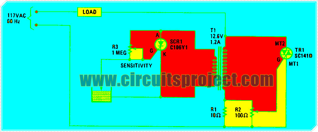
This is a simple Project of Water level Sensor and Controller Circuit Diagram. When the water level is low, the probe is out of the water and SCRl is triggered on. It conducts and imposes a heavy load on transformer Tl`s secondary winding.
Water level Sensor and Controller Circuit Diagram
That load is reflected back into the primary, gating triac TRl on, which energizes the load. If the load is an electric valve in the water-supply line, it will open and remain open until the water rises and touches the probe; this shorts SCRl`s gate and cathode, thereby turning off the SCRl, which effectively open-circuits the secondary. That open-circuit condition, when reflected back to the primary winding, removes the triac`s trigger signal, thereby turning the water off.


0 comments:
Post a Comment